Posts

Showing posts from March, 2018

Lab 5: Mesh Analysis

Image
Lab 5: Mesh Analysis Joel Cook March 13, 2018 Purpose: The purpose of this lab is to analyze different circuits using mesh analysis to solve for unknown quantities before building and measuring the quantities to compare against predicted values. Mesh Analysis I: We analyzed the circuit in the diagram and predicted that the voltage drop across the 6.8k ohm resistor would be 4.2V and across the 20k ohm resistor would be 2.38V. I performed the mesh analysis by inspection, which means finding the current in each loop by summing the resistors in the loop, subtracting the resistors shared with other loops and accounting for the power supplies. The matrices generated can be solved by hand using reduced row echelon form or using a calculator's matrix functions.  The measured voltages were 2.36V and 4.36V, respectively. The predicted voltage was within 4% of the measured voltage. Mesh Analysis II: For the second circuit diagram, we used mesh analysis an...

Lab 4: Nodal Analysis III

Image
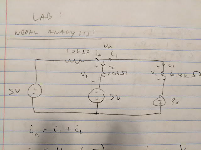
Lab 4: Nodal Analysis III March 8, 2018 Purpose: In this lab, we use nodal analysis to analyze a circuit with multiple sources to predict currents and voltages. Next we construct the circuit and take measurements to confirm our predictions. We analyzed the following circuit: By nodal analysis, we find the voltage, Vc, as the only unknown. We calculated the voltage to be 2.408V, as shown below: The lab asked for voltage V1 which is Vc-0 or 2.408V. We were also asked for current, I1, which we calculated to b2 0.272 mA. Next we constructed the circuit and measure V1 and I1 directly. As shown, we measured the voltage to be 2.45V, a difference of 1.7% from predicted, and 0.35mA, a difference of 22%. Conclusion: The lab was very successful in predicting the voltage drop across a resistor by nodal analysis. Although the difference between actual and expected current was more than 20%, it was still an acceptable means of predicting cur...

Lab 3: Nodal Analysis

Image
Lab 3: Nodal Analysis March 6, 2018 Purpose: In this lab we use nodal analysis techniques for circuits with multiple power supplies. By analyzing the currents at circuit nodes, we can calculate what the voltage at those nodes will be. For the pre-lab we analyze circuit on paper before building the circuit, taking measurements and comparing results. Below is the pre-lab analysis that was conducted on the circuit shown: The voltages predicted were 2.36V for V1 and 4.36V for V2. Next we constructed the circuit as shown below: We used the Analog Discovery tool to provide the required power supplies and took measurements with a DMM. We measured the voltages as 2.34V at V1 and 4.33V at V2. This is a difference of 0.8% for V1 and and 0.7% for V2.  Conclusion: The results for the measured and expected voltages are very close and better than I anticipated. The lab was successful and shows that nodal analysis is an accurate means of analyzing a ci...

Lab 2: Practical Voltage and Current Measurement

Image
Practical Voltage and Current Measurement Joel Cook March 1, 2018 Purpose:  The purpose of this lab is to construct a circuit and take measurements to explore the behavior of non-ideal voltage measurements. Taking measurements of a circuit affects the circuits operation and this help will help determine to what extent. Data: Pre-lab: We began by calculating the measured voltage, V out, of the circuit with an ideal voltmeter that contributes no resistance to the circuit. As shown, the voltage measured would be 2.5V. We calculated the equivalent resistance with the attached DMM in terms of Rm, the internal resistance of the meter. Data: We constructed the circuit as shown in the photo below. The resistors used are 10Mohm resistors. We measured the voltage with the following tool and laptop: We read 0.335 Volts as shown below. We estimated the internal resistance of the analog device as shown: We calculat...

Lab 1: Solderless Breadboards, Open Circuits and Short Circuits

Image
Lab 1: Solderless Breadboards, Open Circuits and Short Circuits Joel Cook February 27, 2018 The purpose of this lab was to familiarize us with the use Breadboards and Digital Multi-meters (DMM) for the purpose of circuit analysis. Data: 1. For the first step, we connected the DMM to two holes in the same row on the breadboard. As shown above, we measured 0.1 ohms. This result is consistent with what we expect as holes in the same row act as a short circuit (are connected) and would have no resistance besides the resistance of the leads of the DMM. 2. For the second step, we connected our DMM to holes on opposite sides of the central channel of the breadboard.  The measured resistance was infinite. This is as expected as the central channel of the breadboard creates an opening in the circuit and the resistance of an open circuit is infinite. 3. For the third step, we connected our DMM to two holes in different rows of the same side of the brea...